
How to georeference a floor plan: control points, rotation and scale
How to georeference a floor plan: control points, rotation and scale, references to trust, common errors, and why it matters for GPS handover and campuses.
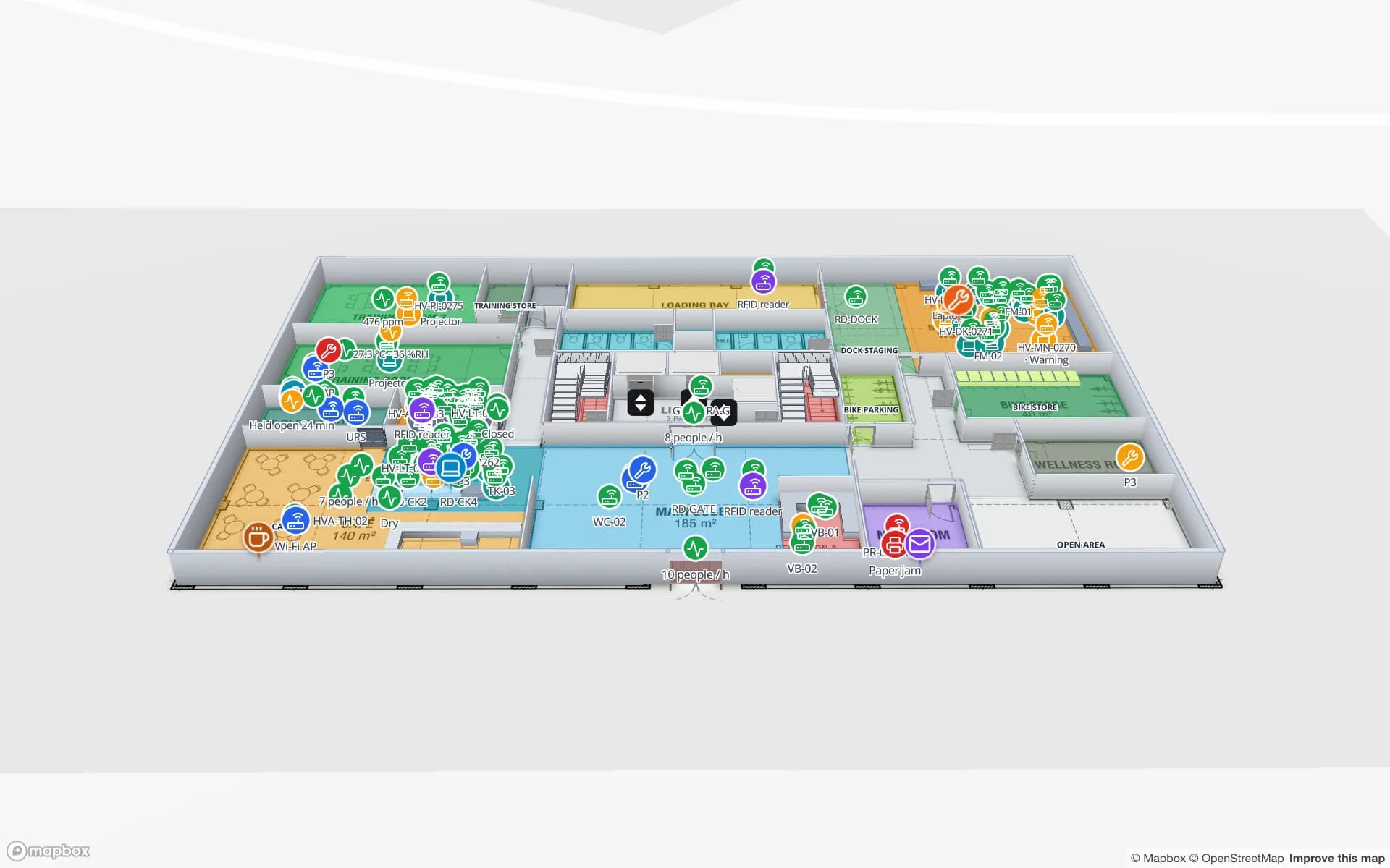
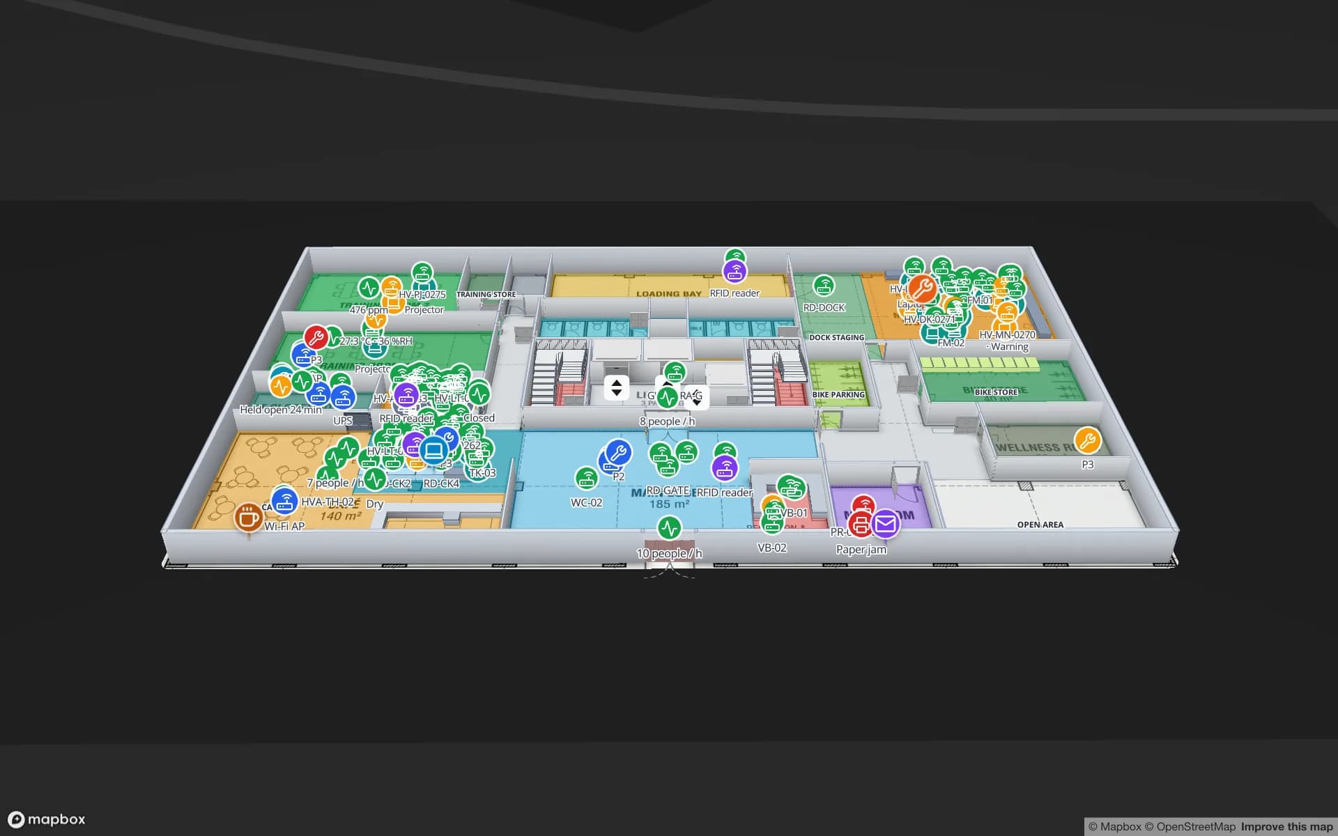
What it means to georeference a floor plan
To georeference a floor plan is to pin it to real-world coordinates, so that every point on the drawing has a latitude and longitude. A floor plan on its own lives in paper or drawing units with its own idea of “up”; once georeferenced, it sits on the map exactly over the building, at the right size and rotation. Spatial Map is a browser-based indoor mapping platform where this is the first step for every floor: you place the plan on a real map and line it up with the building before anything is drawn on it.
Mathematically, georeferencing a clean plan needs four numbers: a shift east–west, a shift north–south, a rotation and a scale. Everything in this guide is about getting those four right, and noticing when a plan needs more than that.
Why georeferencing matters
- Outdoor context. Car parks, yards, gates and neighbouring buildings appear around the plan where they really are.
- GPS handover. At an entrance, an outdoor GPS position and the indoor map agree, so a person or vehicle does not jump across the site.
- Positions from other systems. RTLS engines, gateways and vehicle trackers often report latitude and longitude; they only land in the right room if the plan is in the right place.
- Several buildings. On a campus or a logistics park, buildings line up with each other and with the roads between them.
- True measurements. Distances, areas and walking times are right, because the map is in metres, not drawing units.
- Exchange with GIS. Shapes drawn on a georeferenced plan can be compared with site and GIS data without a manual transformation.
Control points and transformations
GIS tools georeference with control points: pairs of “this point on the drawing is this point on the ground”. The number of pairs decides which transformation you can solve, and the right transformation depends on how clean the plan is.
| Transformation | Minimum points | Corrects | Use for |
|---|---|---|---|
| Similarity (shift, rotate, uniform scale) | 2 | Position, rotation, size | CAD exports and vector PDFs — the plan is already square |
| Affine | 3 | Plus different scale in x and y, and skew | Scans and photocopies that were stretched slightly |
| Polynomial / rubber-sheet | 6 or more | Plus curved distortion | Rarely right for buildings; it bends walls to fit errors |
- 1Pick points far apart
Opposite corners of the building, not two corners of one wall. Errors in angle shrink with distance.
- 2Pick points you can see on both
Outer building corners at ground level, column grid intersections, the corners of a stair core.
- 3Use more than the minimum
With a third or fourth point, the tool can report the leftover error (often as an RMS value). A single point with a large error is usually a misidentified point.
- 4Check a point you did not use
The far corner of a loading dock or a gate post: if it lines up, the result is good.
What to align against — and what not to trust
| Reference | Trust it? | Why |
|---|---|---|
| Survey or site plan coordinates in the CAD file | Yes, if the coordinate system is known | The most accurate reference you will get |
| Building footprint on the basemap | Usually | Good for low buildings; check against imagery |
| Satellite or aerial imagery | With care | It can be offset by a metre or more, and tall buildings lean: you see the roof, displaced from the footprint |
| The north arrow on the plan | No | Often “plan north”, drawn square to the building, not true north |
| A magnetic compass reading on site | No | Magnetic north differs from true north, and steel structure deflects compasses |
Common errors and how to spot them
| What you see | Likely cause | Fix |
|---|---|---|
| One end lines up, the other is off by a constant angle | Rotation taken from the north arrow | Rotate to the building’s long façade instead |
| Lines up at one corner, too big or small at the far corner | Wrong scale or drawing units | Re-import with the right scale or units, or use a measured dimension |
| Everything shifted by the same few metres | Aligned to offset imagery or a leaning roof | Align to the footprint at ground level |
| Upper floor does not sit over the ground floor | Each floor aligned to its own outline | Align every floor to the same stair core or column grid |
| Walls look bent near the edges | Lens distortion in a photographed plan | Rescan or rephotograph; do not fix it with a rubber-sheet transform |
How Spatial Map’s floor plan tool does it
Spatial Map does not have a control-point solver. Georeferencing is done directly on the map, which for clean plans amounts to a similarity transformation done by eye — and the scale part is usually already solved by the import.
- 1Fix the scale at import
A PDF sheet gets its size from its drawing scale or a known width; a DWG from its drawing units. An image gets its real Width (or Height) typed in the panel, with the aspect ratio locked.
- 2Find the building and drop the plan
Search the address with Search places…, then drag on the map to place the plan. For a scaled PDF or DWG, only the position follows your drag.
- 3Make it see-through
Lower Opacity so the basemap’s building outline shows through the plan.
- 4Rotate
Use the Rotation slider (−180° to +180° in 0.5° steps) or [ and ] for 1° (Shift for 15°). Match the longest straight façade first.
- 5Nudge
Arrow keys move the plan 0.5 m, Shift 5 m. Check the far corner, then the opposite one.
The Position section shows the latitude and longitude of the plan’s centre, which is useful for writing down where a floor sits. Stack further floors at the same spot with their own Elevation, aligning each to the same stair core; hide or fade the others while you work. Every control is in the floor plan tool guide, and the scale side in the PDF and DWG import guide.
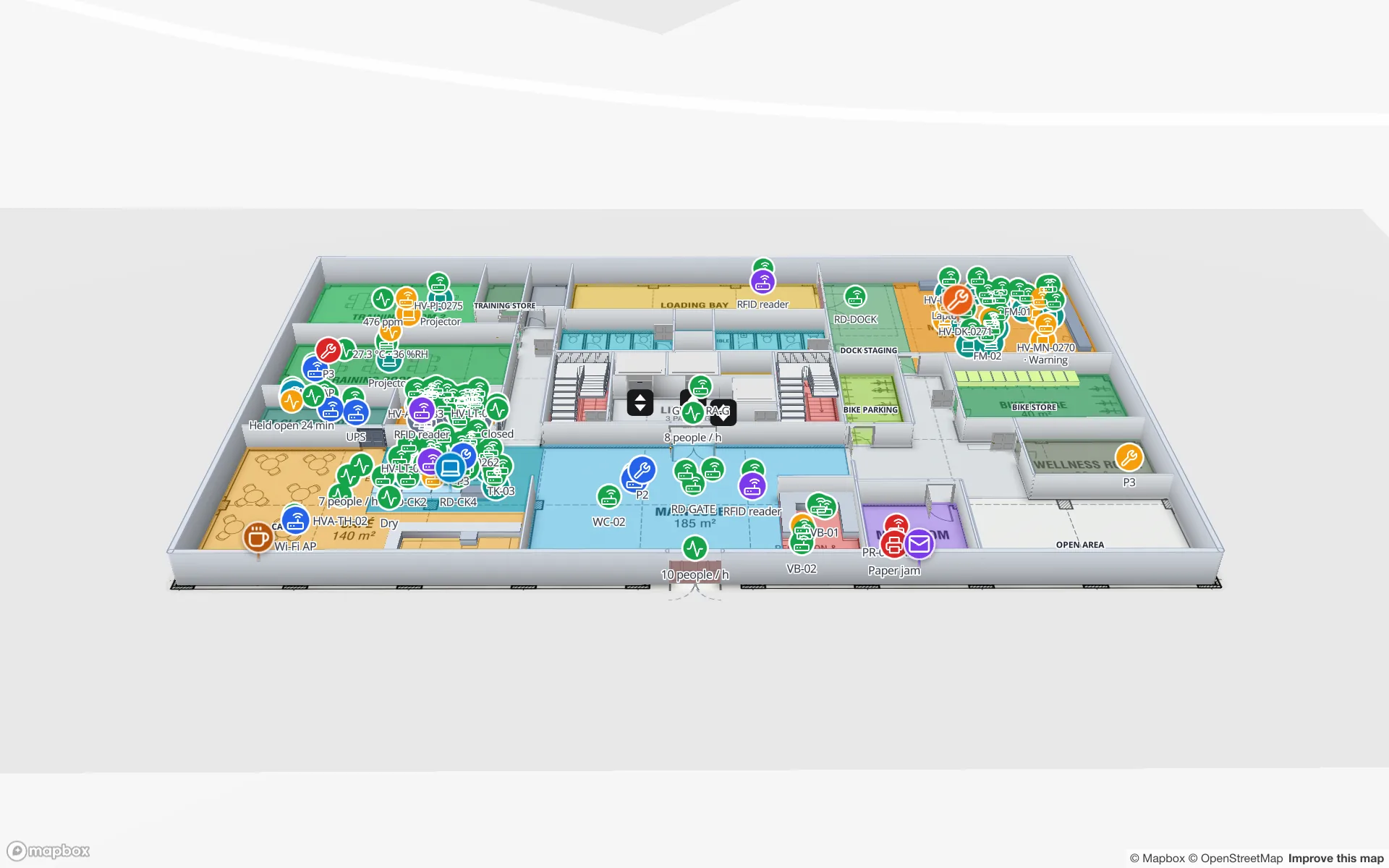
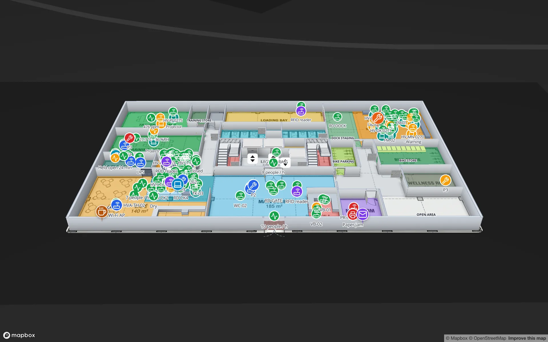
Once the plan is in place, everything drawn on it — rooms, walls, racks, doors — inherits the georeference, and live positions in latitude and longitude land in the right room. If a newer drawing arrives, Replace image swaps it in at the same position and size. The full path from file to working map is on floor plan to indoor map; Spatial Map’s 7-day free trial covers up to 5 facilities, no card needed.
Try the platform your data belongs on.
Spatial Map turns spreadsheets, sensor streams, and CAD drawings into one live 3D facility view — nothing to install, seven-day free trial.
Keep reading
- TutorialBLE gateway for asset tracking: placement, backhaul, MQTT and the mapGateways are where BLE tracking succeeds or fails. How to place them, connect them, turn their MQTT or HTTP messages into zones, and write the result to a live floor plan.
- TutorialHow to convert a PDF floor plan to a 3D map of a commercial buildingA PDF knows its paper size but not its scale. How to get the scale right, clean the sheet, align it to the site and turn walls, racks and floors into a true-scale 3D building.
- TutorialHow to digitize a paper floor plan: scan, scale, traceFrom an old blueprint or a photo of an evacuation plan to a usable digital plan: capture, perspective correction, scale, the CAD question, and the step to an indoor map.