
How to digitize a paper floor plan: scan, scale, trace
How to digitize a floor plan from paper or a photo: scanning, perspective correction, getting the scale right, when to redraw in CAD, and turning it into a map.
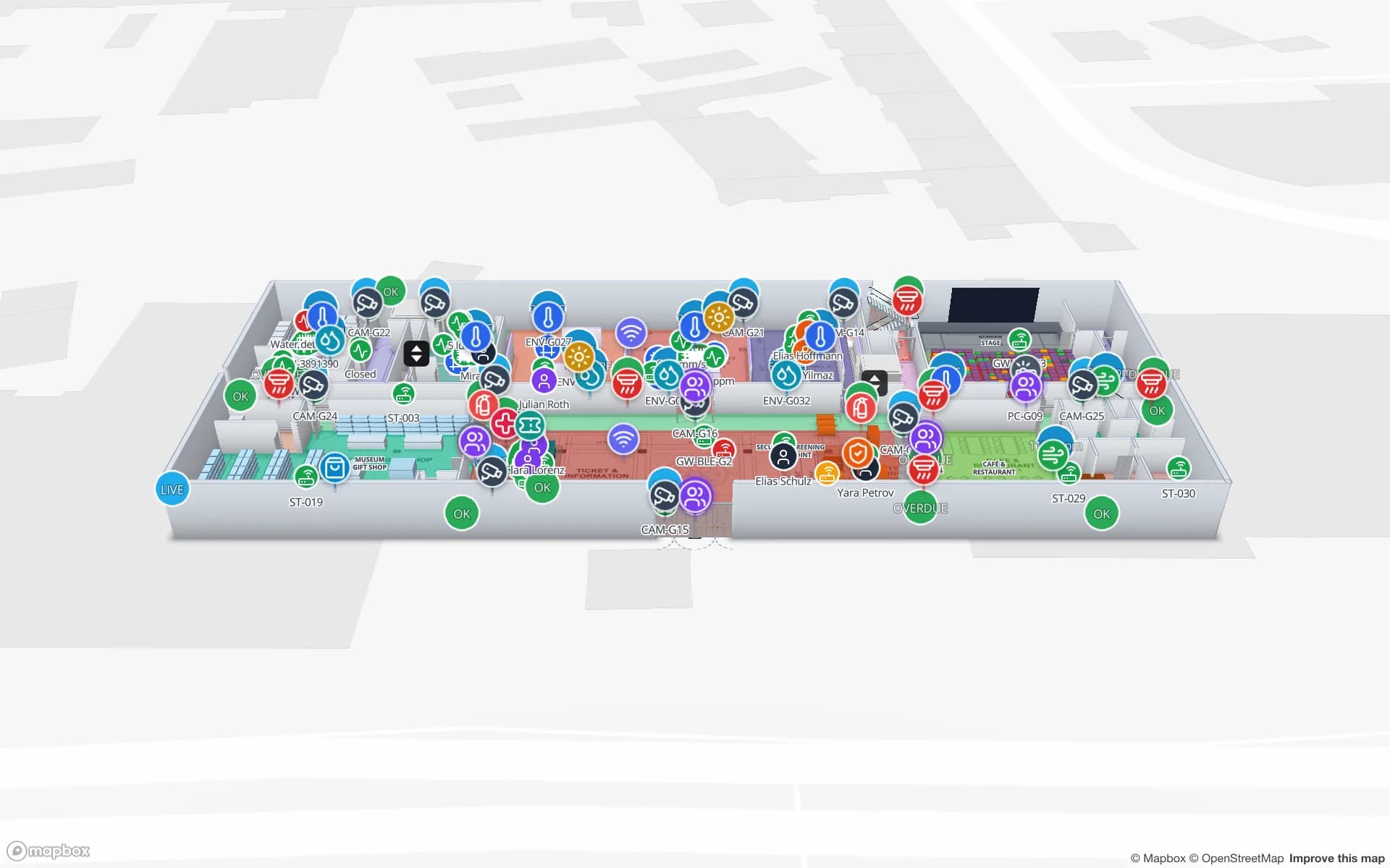
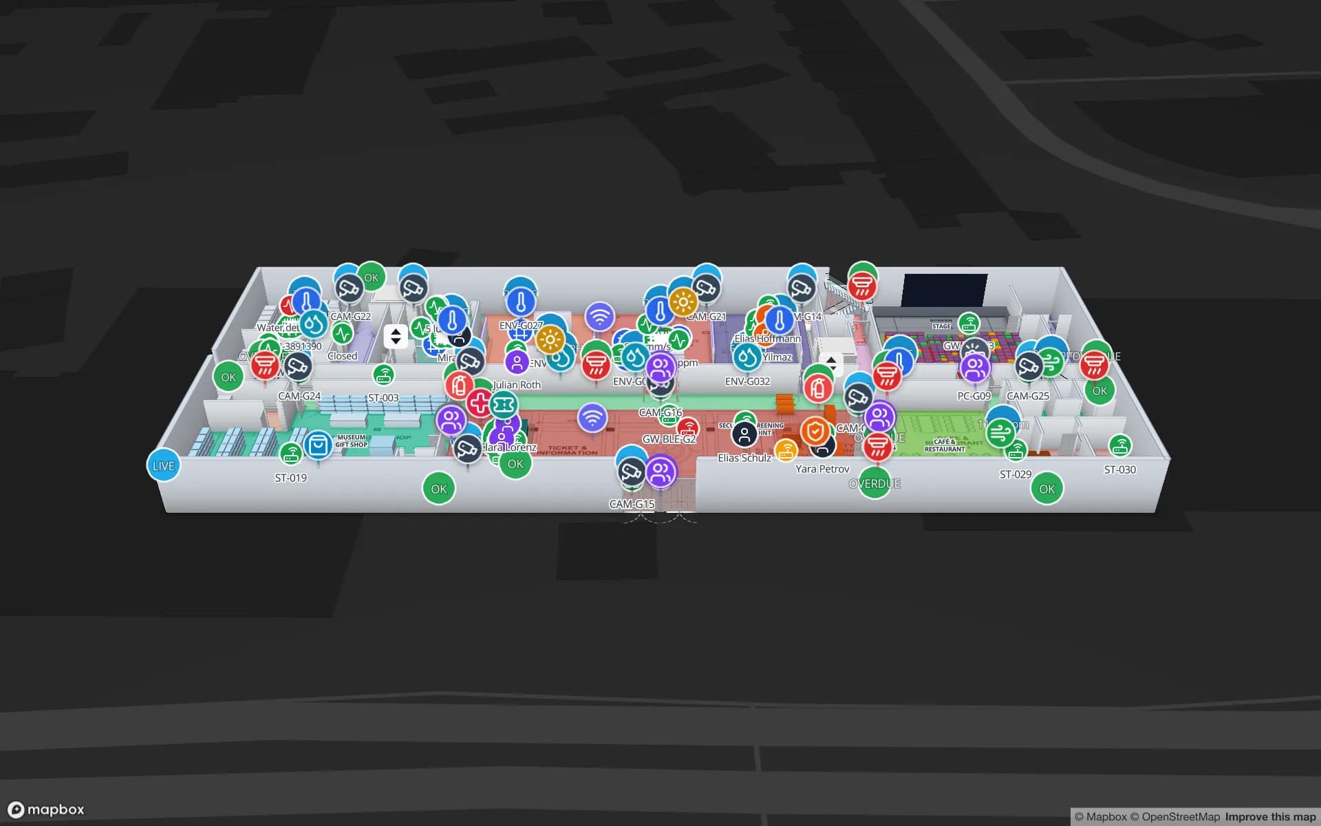
How to digitize a floor plan: three levels
To digitize a floor plan is to turn a paper drawing — an old blueprint, a framed evacuation plan, a photocopy from the landlord — into something a computer can use. Spatial Map is a browser-based indoor mapping platform that takes a scanned or photographed plan as an image, places it at real-world scale on a map, and turns it into a multi-floor indoor map with live data. Before you start, decide how far you need to go:
| Level | What you end up with | Good for |
|---|---|---|
| 1. Digital image | A clean, square, scaled scan or photo (PNG, JPEG, PDF) | Archiving, sharing, printing, the base for tracing |
| 2. CAD redraw | Vector lines and dimensions in a CAD drawing | Building works, permits, consultants, precise dimensions |
| 3. Indoor map | Rooms, walls, doors, floors and racks as named objects at real coordinates | Operations, directions, live data, reports |
Level 1 is always needed. Levels 2 and 3 are different jobs: you rarely need a CAD redraw just to get an indoor map, and a CAD drawing on its own still is not one.
Step 1: scan or photograph the plan
A scanner gives the best result because the sheet is flat and the optics are square to it. A phone photo works for small plans and for plans you cannot take off the wall.
| Sheet | Best capture | Settings |
|---|---|---|
| A4 or A3 | Flatbed scanner, or a phone photo | 300 dpi, greyscale; 400 dpi if the text is tiny |
| A2 to A0, blueprints | Large-format scanner (print and copy shops have them) | 300 dpi, greyscale or colour if colours carry meaning |
| Wall-mounted evacuation plan | Phone photo, straight on | No flash on glass; step back and zoom in slightly to reduce lens distortion |
| Torn or folded sheets | Flatten under glass, scan in parts if needed | Overlap the parts generously |
- Keep the edges. Include all four corners of the sheet in the photo; they are your reference for squaring it.
- Light it evenly. Two light sources at an angle beat one overhead lamp; shadows across the sheet become grey smudges later.
- Hold the camera parallel. Every degree of tilt has to be corrected afterwards, and corrections cost sharpness.
- Save losslessly. Keep the master as PNG or TIFF; JPEG artefacts blur thin lines.
Step 2: correct perspective, crop and clean
- 1Correct perspective
Document-scanner apps do this automatically when they detect the page. In an image editor, use the perspective or “warp” tool and pull the four sheet corners to a rectangle with the sheet’s real proportions (an A-size sheet is 1 : 1.414).
- 2Check the right angles
Long walls should be straight and corners square. Curved lines near the edges mean lens distortion; retake from further away rather than fix it.
- 3Crop and straighten
Crop to the plan area plus the scale bar, and rotate so the main walls are horizontal.
- 4Clean the background
Use levels or a threshold to turn yellowed paper white and lines black. Remove stains and folds with a soft eraser, not by redrawing.
- 5Export a working copy
Keep the master. For map use, export a copy of at most 4096 px on its long edge — larger images do not display on some devices.
Step 3: establish the scale
A digital image has pixels, not metres. You need one trustworthy real-world length to convert between them — and the written scale on a paper plan is the least trustworthy, because photocopiers and printers quietly enlarge or shrink.
| Source of scale | How reliable |
|---|---|
| A dimension you measured on site with a laser measure | Best — measure the longest straight wall you can |
| A dimension written on the plan | Good, if it is between two clear points |
| A graphic scale bar | Good — it shrinks and grows with the copy |
| Column grid spacing from another drawing | Good for structural buildings |
| “Scale 1:100” printed on a copy | Poor — only true at the original paper size |
Measure the reference in pixels, divide by its real length, and you know the size of the whole image. For example, a 40 m wall that is 1,600 px long means 40 px per metre, so a 4,000 px-wide image covers 100 m. Check a second dimension in the other direction: if it disagrees, the perspective correction is off.
Step 4: redraw in CAD, or trace straight into a map?
| Redraw in CAD when… | Trace straight into an indoor map when… |
|---|---|
| Building works, permits or a fit-out are coming | The plan is for operations, directions or live data |
| Consultants will exchange the drawing | The people using it are on site, not in a design office |
| You need dimensions to the centimetre | Room-level and rack-level accuracy is enough |
| Fire or evacuation plans must follow a drawing standard | You want a 3D map in a browser this week |
Automatic raster-to-vector converters exist, and they help with clean drawings. On old, hand-drawn or stained plans they produce many short, broken lines that take longer to fix than to trace. Either way, walk the building: paper plans are often decades behind the walls.
Step 5: from the digitized plan to an indoor map
In Spatial Map, upload the cleaned image (PNG, JPEG, GIF or WebP) in the floor plan tool and drag a box on the map to place it. Then type its real Width — with Lock aspect ratio on, the height follows — lower the Opacity, and rotate and nudge it until it sits on the building. The floor plan tool guide covers every control.
Next, let AI Map draft the floor from the image: walls, doors, racks, labels, areas, stairs, lifts and escalators appear on the map for review, and you add them all or kind by kind. The cleaner the scan, the cleaner the draft — which is the practical reward for steps 1 and 2. Fix and add what is missing with the drawing tools, name the rooms, and the plan is now a map. See AI floor plan mapping.
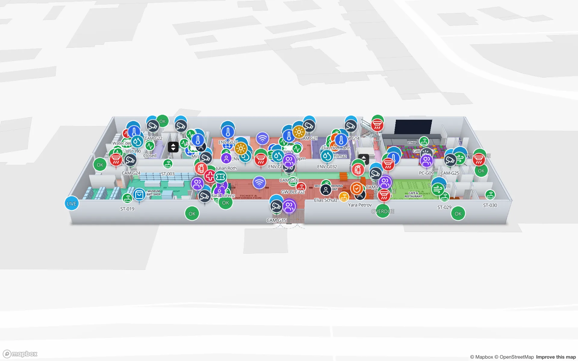
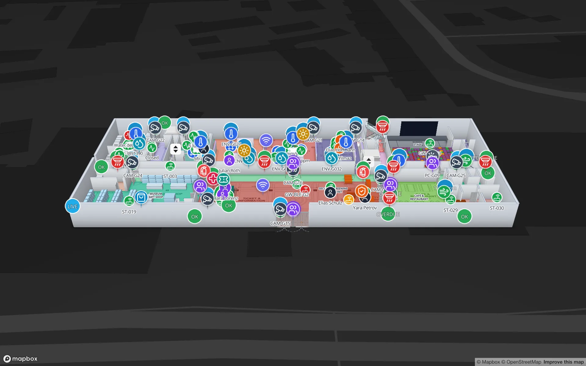
If you later receive a better scan or a CAD drawing, Replace image swaps the picture while keeping its position and size, so everything traced on top stays aligned. The full path from any kind of plan is on floor plan to indoor map, and the 7-day free trial covers up to 5 facilities with no card.
Try the platform your data belongs on.
Spatial Map turns spreadsheets, sensor streams, and CAD drawings into one live 3D facility view — nothing to install, seven-day free trial.
Keep reading
- TutorialBLE gateway for asset tracking: placement, backhaul, MQTT and the mapGateways are where BLE tracking succeeds or fails. How to place them, connect them, turn their MQTT or HTTP messages into zones, and write the result to a live floor plan.
- TutorialHow to convert a PDF floor plan to a 3D map of a commercial buildingA PDF knows its paper size but not its scale. How to get the scale right, clean the sheet, align it to the site and turn walls, racks and floors into a true-scale 3D building.
- TutorialHow to georeference a floor plan: control points, rotation and scalePinning a floor plan to real-world coordinates takes four numbers: position, rotation and scale. How to choose control points, what not to trust, and how to spot the usual errors.